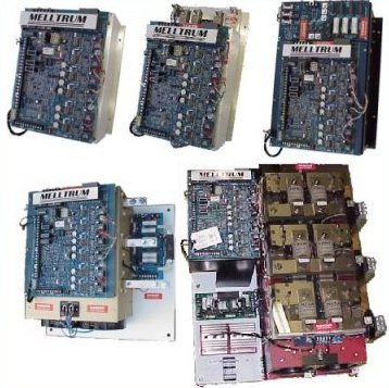
|
|
 |
240 VAC
HP |
460 VAC
HP |
ARM
VOLTS
DC |
FIELD
VOLTS
DC |
100% DC
ARMATURE
CURRENT |
MODEL
NUMBER |
PART
NUMBER |
| 5 - 10 |
5 - 20 |
240/500 |
150/300 |
34 |
MELLTRUM 1 |
222-8420C |
| 15 - 30 |
25 - 60 |
240/500 |
150/300 |
102 |
MELLTRUM 2 |
222-8460 |
| 40 - 50 |
75 - 100 |
240/500 |
150/300 |
160 |
MELLTRUM 2+ |
222-8460+ |
| 40 - 60 |
75 - 125 |
240/500 |
150/300 |
202 |
MELLTRUM 3 |
222-8410 |
| 75 - 125 |
150 - 250 |
240/500 |
150/300 |
424 |
MELLTRUM 4 |
222-8425 |
| 150 |
300 |
240/500 |
150/300 |
480 |
MELLTRUM 4+ |
222-8430 |
| 200 |
400 |
240/500 |
150/300 |
640 |
MELLTRUM 4+4 |
222-8440 |
| 250 - 350 |
500 - 700 |
240/500 |
150/300 |
1200 |
MELLTRUM 5 |
222-8470 |
| NOTE: OTHER LINE VOLTAGES AVAILABLE 208, 380, 416 |
GENERAL DESCRIPTION
- Six SCR Full Wave Power Bridge - Provides improved form factor for greater efficiency of operation.
- Inner Loop Current Regulator - Inherent high band width capability for fast response.
- Separately Adjustable Linear Accel/Decel Control - 2-30 seconds.
- Speed Regulator - 2% accuracy using armature voltage feedback with IR compensation or 1% accuracy with tachometer feedback. Regulation may be improved be selecting the proper motor mounted tachometer.
- Current (Torque) Regulator - With less than 1% error in the armature current regulator, the operator can control motor torque instead of speed.
- DC Overload (Armature) - Senses overcurrent with inverse time trip.
- AC Line Connections - The MELLTRUM is completely insensitive to AC line phase sequencing.
- Heat Sink Thermal Switch - Prevents long term thermal damage to SCRs due to loss of cooling or overheating (not included in MELLTRUM 1, which has no cooling fan).
- Fault Trip - Instantaneous fault trip protection circuit designed to shut the drive down if any of the following conditions occur:
- Fields Loss (Defeatable)
- Heat Sink Overtemperature (except MELLTRUM 1)
- Instantaneous Overcurrent (300% of rated)
- Inverse Time DC Overload
- Test/Reset - If any of the previously described fault conditions occur, the drive can be reset by depressing the RESET button on the main circuit board. The fault light will not reset if the fault condition is still present.
- Field Loss Protection - Provides protection against runaway, due to loss or motor field, by shutting down the drive.
- Dual Frequency Operation - Can be operated from 50 or 60Hz AC power supplies by a simple jumper change.
- Exclusive Static Adjustable Current Limit - Allows static setting of desired current limit value without applying DC power and without a connected output load. A current limit indicating light is also supplied to provide visual indication when the preset current limit value is reached.
- Isolated Control Circuitry - High impedance resistor isolation of the control circuits from the power bus provides protection in the event of a ground fault. The ammeter, speed potentiometer, and tachometer are not at line potential. Current transformers on each of the three AC lines provide an isolated armature current signal to the main circuit board. When tachometer feedback is employed, the drive control circuits are completely isolated form the AC power bus.
- Jog at Preset Speed - Separately adjustable from 0 to 30% of base speed.
- Control Regulator Circuit Board - Common circuitry throughout the MELLTRUM line of controls. MELLTRUM 1,2, 2+, and 5 use the same board. MELLTRUM 3, 4, and 4+ boards have an extra one inch margin on the left and right sides but all are electrically identical.
- Instantaneous Overcurrent Protection - Senses armature fault currents quickly to protect both semiconductors and motors against damaging current levels.
- High Speed Current Limiting SCR Semiconductor Fuses - Provides the utmost in fuse coordination and protection of the SCRs and motor with positive circuit clearing for both AC and DC faults.
- AC Line Filter and Transient Voltage Suppressor Network - Eliminates interaction between other drives or AC equipment. *
- Standard Adjustments - Maximum speed, minimum speed, jog speed, separate acceleration and deceleration time, stability, current limit, and IR compensation.
*Note: Severe System Applications may require additional electrical equipment to insure proper drive operation.
|
| MODEL |
HORSEPOWER
RATING |
AC POWER
INPUT |
DC POWER
OUTPUT |
FIELD
OUTPUT |
HEAT
LOSS |
240/3/60 |
430/3/60 |
VOLTS |
MAX
AMPS |
VOLTS |
MAX
AMPS |
VOLTS |
MAX
AMPS |
MAX
WATTS |
| MELLTRUM 1 |
5-10HP |
5-20HP |
240/480 |
23 |
240/500 |
34 |
150/300 |
6 |
117 |
| MELLTRUM 2 |
15-30HP |
25-60HP |
240/480 |
84 |
240/500 |
102 |
150/300 |
6 |
367 |
| MELLTRUM 2+ |
40-50HP |
75-100HP |
240/480 |
139 |
240/500 |
160 |
150/300 |
10 |
502 |
| MELLTRUM 3 |
40-60HP |
75-125HP |
240/480 |
174 |
240/500 |
202 |
150/300 |
16 |
608 |
| MELTLRUM 4 |
75-125HP |
150-250HP |
240/480 |
343 |
240/500 |
424 |
150/300 |
16 |
1100 |
| MELLTRUM 4+ |
150HP |
300HP |
240/480 |
402 |
240/500 |
480 |
150/300 |
16 |
1300 |
| MELLTRUM 4+4 |
200HP |
400HP |
240/480 |
536 |
240/500 |
640 |
150/300 |
16 |
1500 |
| MELLTRUM 5 |
250-350HP |
500-700HP |
230/460 |
940 |
240/500 |
1200 |
150/300 |
25 |
3000 |
SERVICE CONDITIONS
- Rated Voltage Input: 240 and 480 volts (203, 380, and 416 volts available, consult factory) (-10, +10%) AC three phase
- Frequency: 50/60 Hz ( 2 Hz)
- Ambient Temperature: 0-40°C (32°F to 104°F)
- Altitude: Sea Level to 3300 Feet
Efficiency at Rated Output:
- Power unit 98% or better depending on selected rating
- Drive system 82% or better depending on selected rating
Input Signal Requirements:
- 10V DC at 1 MA (nominal) for maximum speed reference
Potentiometer:
- 2000 Ohms, 2 Watt
Main Circuit Board Indicators - Light emitting diodes (LED’s) on the main circuit board for:
- AC Power On
- DC Power On
- Current Limit
- DC Overload
- Phase Loss
Fault Trip In addition, six separate LED’s indicate that each firing circuit is producing pulses.
Performance Specifications:
- Controlled Speed Range: 20:1 for basic control, may be extended to 200:1 with modification kit.
- Speed Regulation:
For a 95% Load Change:
Voltage Regulated-2-5% of maximum speed
Speed Regulated -1% of maximum speed (with any AC or DC Tachometer)
For All Other Variable Drives:
Voltage Regulated-changes up to 15% of top speed can result from temperature variations, voltage and frequency variations and drift.
Speed Regulated-Any AC Tachometer-2%
Speed Regulated-Any DC Tachometer-1%
- May be modified to achieve 0.1% due to 95% load change and 0.15% due to all other variables.
- Overlaod Capacity: 150% of Rated Current for 1 Minute
- Service Factor: 1.0
Adjustment Ranges (Typical)
- Minimum Speed: 0 to 30% rated speed
- Maximum Speed: 60 to 120% rated speed
- Acceleration Time: 2 to 30 seconds (linear)
- Jog Speed: 0 to 30% rated speed
- IR Compensation: 0 to 22% rated voltage
- Current Limit: 0 to 150% rated current
|
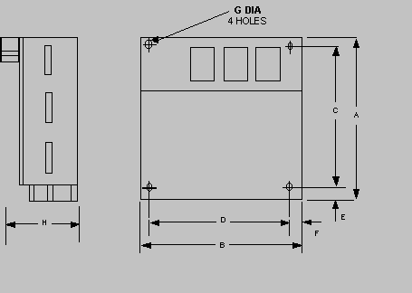
| MOUNTING DIMENSIONS FOR MELLTRUM |

| DRIVE |
A |
B |
C |
D |
E |
F |
G DIA |
H |
WT.-LBS. |
| MELLTRUM 1 |
14.50 |
11.63 |
10.50 |
10.75 |
2.00 |
0.44 |
.281 |
8.00 |
22 |
| MELLTRUM 2 |
18.00 |
11.63 |
14.00 |
10.75 |
2.00 |
0.44 |
.281 |
8.00 |
26 |
| MELLTRUM 2+ |
18.00 |
11.63 |
14.00 |
10.75 |
2.00 |
0.44 |
.281 |
8.00 |
29 |
| MELLTRUM 3 |
22.00 |
15.63 |
12.75 |
13.63 |
4.75 |
1.00 |
.321 |
9.00 |
45 |
| MELLTRUM 4 |
21.00 |
21.00 |
19.25 |
19.25 |
0.88 |
0.88 |
.5 |
13.00 |
70 |
| MELLTRUM 4+ |
21.00 |
21.00 |
19.25 |
19.25 |
0.88 |
0.88 |
.5 |
13.00 |
80 |
| MELLTRUM 4+4 |
21.00 |
21.00 |
19.25 |
19.25 |
0.88 |
0.88 |
.5 |
13.00 |
80 |
| MELLTRUM 5 |
33.00 |
27.00 |
31.25 |
25.25 |
0.88 |
0.88 |
.5 |
16.25 |
200 |
|
REV DATE: 7/23/2012
©2020 SCR Controls, Inc.
3479 Gribble Rd., Matthews, NC 28104
PO Box 2368, Indian Trail, NC 28079
email:
|
|
|
This sight is viewed best viewed with the latest versions of Netscape,
Internet Explorer and Chrome. |
A. Manufactured items:
MELLTRUM (SPECTRUM REPLACEMENT) ES100A ES125A ES150A ES150ARG ES200A ES200ARG ES222 ES2300RG ES2600RG ES2700 2400-8000 2400-8001W 2450-8000W
2450-8001W 2450-8010W 2450-8015W
EDDY CURRENT CLUTCH 1235 367 FOCUS 2 FOCUS1 FOCUS 1 REPLACEMENT BOULIGNY MARK ANDY SECO BALDWIN ENKEL CUSTOM AUTOMATION SYSTEMS MULTI DRIVE SYSTEMS ERC REPLACEMENT.
|


